
DAF CF65, CF75, CF85 Wiring Diagram. Electrical Sysytem
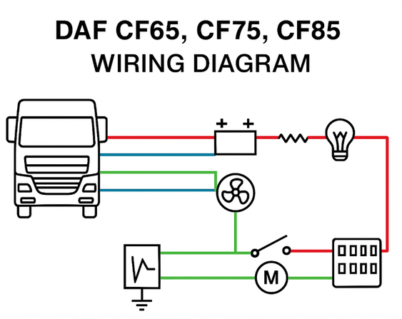
This page presents a complete electrical system diagram for the DAF CF65, CF75, and CF85 trucks. These diagrams are intended for technicians, mechanics, and electricians servicing and diagnosing CF series Truck.
- DAF CF electrical wiring diagram
- DAF CF65 wiring diagram
- DAF CF electrical system wiring CF65 CF75 CF85 chassis 0E621376
- DAF CF65 CF75 CF85 fuse box layout
- DAF CF alternator wiring
- DAF CF CAN bus wiring
- DAF CF central junction box wiring
Full Wiring Diagram
| Password for PDF: truckfixdiagn.com | |
| CF65 CF75 CF85 Technical data. Diagnostics | Download |
| CF65 CF75 CF85 Components | Download |
| CF65 CF75 CF85 Wiring repair | Download |
| CF65 CF75 CF85 Batteries. Charging, Cheking, Storage | Download |
| CF65 CF75 CF85 Connection of accessories | Download |
| CF65 CF75 CF85 Reading diagrams. Marking, Reading Circuit Diagram | Download |
| CF65 CF75 CF85 Location of components | Download |
|
CF65 CF75 CF85 Location of connectors |
Download |
| CF65 CF75 CF85 Electrical system. Circuit Diagram | Download |
| CF65 CF75 CF85 Changes in the electrical system | Download |
| CF65 CF75 CF85 Electrical system: options and special applications | Download |
| CF65 CF75 CF85 System Manual VIC+DIP-4 | Download |
| CF65 CF75 CF85 CAN data manager (CDM) | Download |
DAF CF65, CF75, CF85 Basic Wiring and Electrical Problems
⚡ Common Electrical Problems for DAF CF65 / CF75 / CF85
1. 🔋 Poor Contacts and Corroded Connectors
Most Vulnerable Areas:
Connectors under the cab and behind the battery box;
Connections near the EBS/ABS unit;
Connectors under the front bumper (headlights, sensors, horn).
Symptoms: False ABS or EBS errors, low voltage, loss of power to headlights or instruments.
Cause: Moisture and salt ingress, poor contact sealing.
Solution: Cleaning, applying contact grease, replacing damaged pins.
2. 💡 Burnt-out and Overheated Wiring in the Fuse Box
The fuse box (cab fuse box) is susceptible to heat and oxidation.
Melted contacts are common in the cabin fan, headlight, heater, or cigarette lighter circuits.
Tip: Regularly check the temperature and condition of the contact pads, especially if you smell melting plastic.
3. ⚙️ Grounding Problems
A common cause of numerous "ghost" errors in electronics is unstable grounding.
Typical symptoms:
"Dancing" instrument readings;
Incorrect switching on/off of lights;
ECU, VIC, ABS, or EBS errors.
Solution: Clean and tighten all ground points, especially on the frame, under the cab, and near the battery.
4. 🧠 VIC (Vehicle Interface Control) Malfunctions
The VIC controls many cabin and instrument cluster functions.
Power surges or poor connections can cause false errors (e.g., "Engine Malfunction," "Low Air Pressure," or "Alternator Fault").
Solution: Check the VIC power and ground, and reprogram or replace if necessary.
5. 🔌 Wiring faults to the taillights and towbar connector
The harness near the rear frame crossmember or near the hitch often frays.
Symptoms: Brake lights and turn signals do not work, and shorts out intermittently in the rain.
Solution: Visual inspection, insulation, and replacement of the harness if damaged.
6. ⚠️ Alternator/Charging Error
Problems may not be with the alternator itself, but with the excitation circuit or the wire from the alternator to the battery.
Sometimes the wiring at the D+ (excitation) terminal breaks or oxidizes.
Result: The charging indicator is on, but the voltage is normal, or, conversely, the alternator is not charging.
Solution: Check the wires and terminals for contact resistance.
7. 💧 Moisture in harnesses and control units
Harnesses under the cabin floor and behind the battery compartment often absorb water.
Moisture can enter the engine ECU or EAS (SCR) through the connectors.
Result: CAN errors, unstable module communication, power limitation.
Solution: Drying, sealing, preventative replacement of seals.
8. 🔄 CAN bus problems
Often an open or short circuit in the CAN-H / CAN-L line.
Symptoms: Loss of communication with the ABS, ECU, VIC, or EAS.
Tip: Check the integrity of the twisted pair (gray/yellow wire) and the resistance between the lines (~60 ohms).