
DAF LF45, LF55 Wiring Diagrams

DAF LF45, LF55 Wiring Diagrams – electrical diagrams for DAF LF trucks. A complete set of electrical diagrams for the DAF LF series trucks. The documentation provides detailed wiring diagrams for the LF45 and LF55, including:
- Starting and charging system;
- Lighting and instrument panel;
- Engine control units (ECU) and fuel system;
- ABS, EBS, and braking systems;
- Air conditioning, heating, and additional equipment;
- CAN bus and electronic modules.
LF45, LF55 All Wiring Diagrams
| Password for PDF: truckfixdiagn.com | |
| LF45, LF55 Technical data. Diagnostics | Download |
| LF45, LF55 Components. Diagnostics in electrical systems | Download |
| LF45, LF55 Wiring Repair. Connectors, Contacts | Download |
| LF45, LF55 Batteries. Charging Batteries. Storage of batteries | Download |
| LF45, LF55 Connection of accessories | Download |
| LF45, LF55 Reading Diagrams. Reading Circuit Diagrams | Download |
| LF45, LF55 Location of components | Download |
| LF45, LF55 Location of connectors | Download |
| LF45, LF55 Electrical System. Circuit Diagram | Download |
| LF45, LF55 Changes in the electrical system | Download |
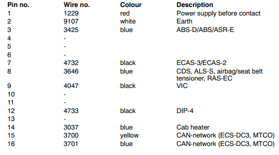
DAF LF45, LF55 Socket Pin. FA/FT
12 V PLUG (A011)
Pin 1 is connected to the 24/12 V converter (12 V before contact) through wire 1153.
Pin 2 is connected to the earth connection of the converter
DIAGNOSTIC SOCKET (A021)
The diagnostic socket is located to the left of the driver’s seat on the floor plate. This is the socket for the DAVIE connection. Power before contact is supplied to pin 1 through fuse E053. Pin 2 is connected to earth. The remaining pins are for communication with the various systems and are connected to those systems.
DRAWN VEHICLE SOCKET (A000) (7-pin)
Pin 1 connected to earth.
When a connection is made between contacts 2 and 1 (marker light/parking light position) by switching on the lighting switch (C622), relay G000 is energised. Relay G000 supplies power to wire 2101 via wire 1000. Via fuses E284 and E283, power is supplied to connector A000 at pin 2 (via wire 2170) and pin 6 (via wire 2169) respectively.


DAF LF45, LF55 ABS/ASR-E Wiring Diagram
Communication failure between the ECU and ABS/EBS.
U-code errors ("loss of communication").
DAF LF45, LF55 Overview of Earthing Points
Location
G516 Central earth, cab
32 These earth points are also usedwith an ABS-D (D941) system
35 Connector 790 is designed for aCB set
68,70 The earth connection ends atconnector 718.
The application wiring harness connected to 718 makes an earth connection directly on the chassis

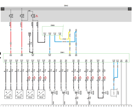
DAF LF45, LF55 CAN Overview
This section diagram gives an overview of all the CAN connections, with wire markings and connector points.
SEE THE SYSTEM MANUAL FOR MORE INFORMATION
2 The terminating resistor is in the automatic transmission wiring harness
8 Electronic unit, automatic gearbox, AGC-T1000/2000 (D936): If MD3060 gearbox is fitted, the
electronic unit is for AGC-A4 automatic gearbox operation (D866)
16 The terminating resistor is in the wiring harness of the ECS-DC3 engine management system
