
Bosch EDC 17 Service Manuals. Wiring Diagram. Pinout

Professional technical manual covering the EDC 17 engine management system used in modern Euro 5 and Euro 6 diesel vehicles.
- Complete wiring diagrams
- Detailed schematic diagrams for all components
- Pinout of control units (ECU), sensors, valves and actuators
- Diagnostic tables and description of typical faults
- System operation algorithms: injection, turbocharging, EGR, DPF, SCR (AdBlue)
- Information on CAN, LIN protocols and diagnostic interfaces
For commercial vehicles and trucks (MAN, DAF, Scania, Iveco):
- EDC17CV41
- EDC17CV44
- EDC17CV52
- EDC17CV54
- EDC17CP64
- EDC17C49
- EDC17C90
| Common Rail system with accumulator fuel injection system EDC17 | Download |
| EDC 17 (D08 Common Rail Engine) Pinout Service Manual | Download |
| Electronic Diesel Control EDC 2001 | Download |
| D20 D26 EDC Service Manual | Download |
| EDC 17 Engine and peripherals. Fault finding | Download |
| EDC 17 For H-Series BSIII and BSIV Engines | Download |
| EDC 17 system for Neptune N4 CRS BSIV engines | Download |
| FPT Iveco Electrical EDC17CV41 | Download |
| NT Bosch Edc17cv41 Irom TC1797 Pinout | Download |
| Pinout Bosch EDC17CV41 irom TC1797 allbrand | Download |
| Bosch Edc17cv52 Irom Tc1797 Deutz 1033 | Download |
| Pinout Bosch EDC17CV52 irom TC1797 Deutz | Download |
| Bosch MEDC17 Bootloader | Download |
| Bosch Edc17cp52 Irom Tc1797 Iveco 1040 | Download |
| Pinout Bosch EDC17C49 irom TC1797 Iveco | Download |
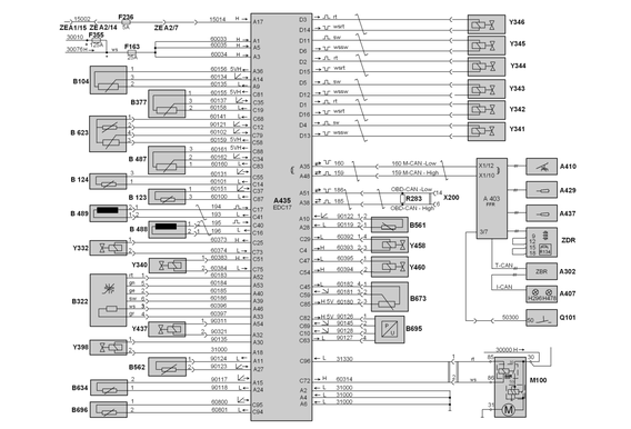


A302 Central Computer 2
A403 Vehicle Control Computer
A407 Instrumentation
A410 Accelerator Pedal
A429 Cruise Control Switch
A435 EDC17 Control Unit
A437 Continuous Brake Pulse Switch
B104 Oil Pressure Sensor
B123 Charge Air Temperature Sensor
B124 Coolant Temperature Sensor
B322 Lambda Sensor
B377 Fuel Pressure Sensor
B487 Fuel Rail Pressure Sensor
B488 Incremental Speed Sensor
B489 Segment Speed Sensor
B561 Exhaust Gas Temperature Sensor Before Filter
B562 Exhaust Gas Temperature Sensor After Filter
B623 Boost Pressure/Temperature Sensor
B634 Exhaust Gas Temperature Sensor After SCR Catalytic Converter
B673 E-AGR Cylinder Travel Sensor
B695 Exhaust Gas Differential/Relative Pressure Sensor
B696 EGR Temperature Sensor EDC17
F163 Engine Control Fuse (Terminal 30)
F236 Fuse, Engine Control (Terminal 15)
F355 Main Fuse 30-2
H296 EDC Indicator Lamp (Malfunction)
H478 Exhaust System Indicator Lamp (MIL)
M100 Starter
Q101 Steering Wheel Lock
R134 EDC Resistor Group
R283 HD-OBD-CAN Terminator
X200 Diagnostic Socket
Y332 Fuel Proportional Valve
Y340 Turbocharger 1 Pulse Valve
Y341 Injector 1 Cylinder
Y342 Injector 2 Cylinder
Y343 Injector 3 Cylinder
Y344 Injector 4 Cylinder
Y345 Injector 5 Cylinder
Y346 Injector 6 Cylinder
Y398 CRT Wastegate Solenoid Valve
Y437 Coolant Solenoid Valve
Y458 E-AGR Proportional Valve
Y460 E-AGR/EVBec Shut-off Valve
ZDR Intermediate Speed Connector


1 CP 3.3 NH quantity-controlled high-pressure pump
2 Fuel proportional valve (Y332)
3 Fuel rail pressure sensor (B487)
4 Pressure limiting valve (DBV 4) integrated in the fuel rail
5 Injectors (Y341 – Y346)
6 High-pressure accumulator (fuel rail)
7 Flame glow plug (R100)
8 Flame start solenoid valve (Y100)
9 Fuel pressure sensor (B377)
10 Hand feed pump with pre-filter
11 KSC fuel assembly
12 HCI metering unit (A1081)
13 HCI injection unit
Main problems of Bosch EDC 17:
1. Clogged diesel particulate filter (DPF)
Cause: short trips, bad fuel, faulty temperature or pressure sensor.
Symptoms: loss of power, regeneration does not start, DPF error.
Often associated with incorrect operation of EDC 17 algorithms.
2. AdBlue / SCR system failures
Problems with the dosing pump, heater, NOx sensors.
Errors: P20E8, P204F, P2200, etc.
Can lead to the launch of the "power limitation mode" (derate).
3. EGR system failures
EGR valve jamming, leaks, position sensor errors.
Check Engine call, overheating, unstable idling.
4. Fuel pressure sensors / Rail / MAP
Often fail after 200-300 thousand km.
Lead to difficult starting, traction failures, injection errors.
5. Control unit (ECU) malfunctions
Internal memory errors, software failures, moisture damage.
Often accompanied by unstable CAN bus operation.
Firmware failure is possible after incorrect chip tuning.
6. CAN/LIN bus errors
Loss of communication with other modules (ABS, TCM, BCM, etc.).
Reason: line break, connector oxidation, power supply problems.
7. Regeneration hang-up / algorithm failures
During long-term driving under partial load conditions.
EDC 17 may "not see" the conditions for DPF regeneration.