
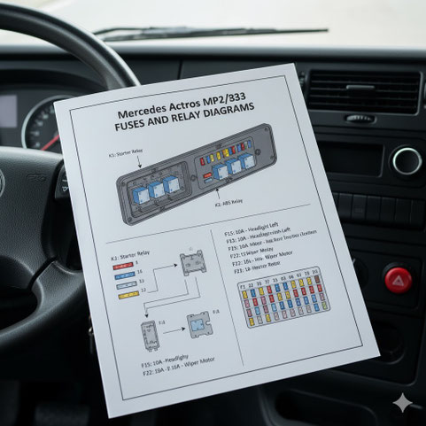
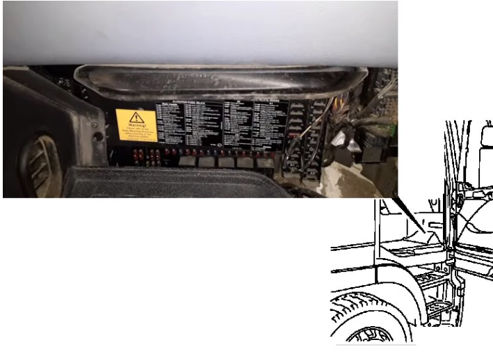
The main fuse and relay box is located in the passenger compartment, in the passenger footwell. Access is provided by removing the protective cover with fastenings on the sides.
Please note that there is no single, general description for all Mercedes Actros MP2 and MP3 models. The purpose of the components and the design of the units may differ from those shown and depend on the year of manufacture and the level of equipment in your vehicle. Please check the current designation against the diagrams on the unit cover.
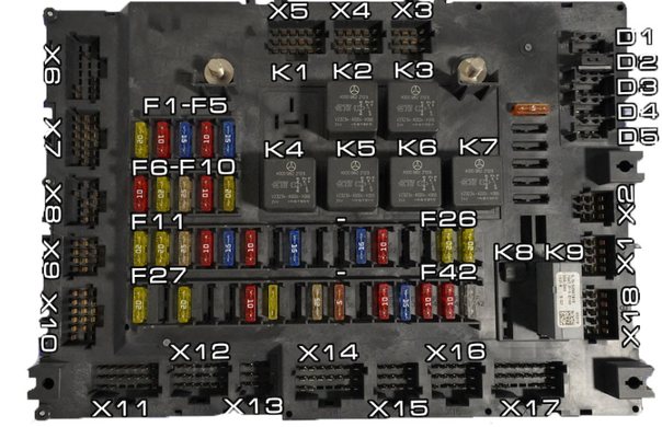
Schematic Diagram
- Fuses
F1 20A Driver's door (door control module), heater control panel, auxiliary heater (hair dryer)
F2 20A Reserve
F3 20A Passenger door (door control module)
F4 15A Gearshift control
F5 20A Trailer socket 15-pin
F6 10A Modular switch panel MSF
F7 30A Retarder control, parameterizable special module, alarm siren, refrigerator, transformer (converter)
F8 30A Front passenger seat with damping suspension, parking air conditioner, rotating beacon, tire pressure monitoring system
F9 30A Trailer socket 7-pin
F10 30A Cruise control with safety distance regulator, remote battery disconnect, tire pressure monitoring system
F11 15A Brake control module System
F12 30A Gearshift Control
F13 20A Audio System, Telematics
F14 10A FR Motion Control Module, Ignition Switch
F15 20A Heater Control Panel
F16 10A Reading Light, Storage Compartment Light
F17 10A Instrument Cluster, Tachograph, Diagnostic Socket
F18 20A Sunroof
F19 30A Brake Control
F20 10A Gearshift Control
F21 10A Engine Management System, Alternator
F22 10A 7-Pin Trailer Socket
F23 15A 15-Pin Trailer Socket, — 7-Pin Trailer Socket
F24 15A Battery Heater, Racor Filter Heater, Solenoid Valve - Dual-Chamber Water Separator
F25 10A Diagnostic Socket
F26 30A Electric Torch Air Heater, Driver's Seat with Damper Suspension, Parking Air Conditioning, Lane Keeping Assist, Electronic-Hydraulic Auxiliary Drive, Electric Sun Visor Motor, Engine Compartment Light, Load Bed Tailgate
F27 20A Heater Control Panel, Telematics
F28 10A Drivetrain Management System
F29 10A Brake System Control
F30 10A SRS Seat Belts, Airbags, Instrument Cluster
F31 10A Audio System, Cabin Temperature Sensor, 24-Volt Power Outlet (Cigarette Lighter)
F32 10A 12-Volt Cigarette Lighter
- Relay
K1 — Trailer Power Outlet
K2 — Heater
K3 — Engine Management/Generator
K4 — Reserve
K5 — Cigarette Lighter Relay
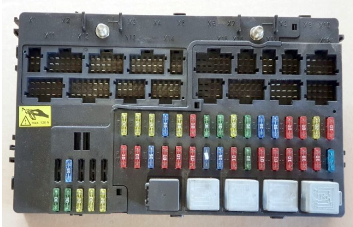
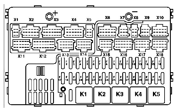
Mercedes Actros MP4 fuse box locations and diagram
Two types of blocks from different manufacturers were installed on Mercedes Actros MP4 vehicles: CONTINENTAL and HELLA
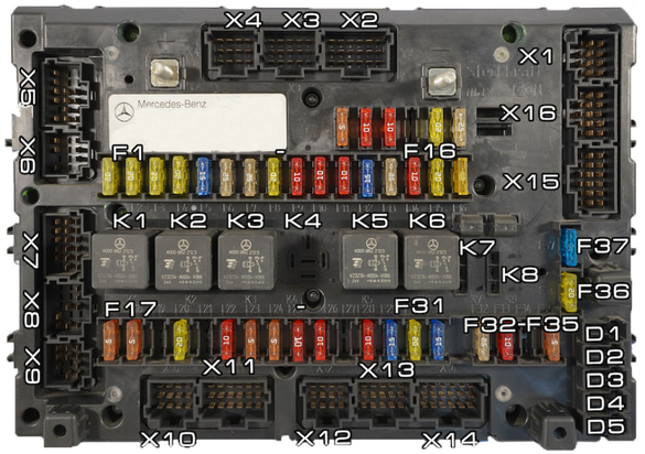
Fuses in module A1:
| Fuse Number | Power Consumer | Nominal Current |
| F1 | Cabin Tilting Mechanism Pump | 5A |
| F2 | Tail Lift | 10A |
| F3 | Beacon Lights | 10A |
| F4 | Working Lamp | 10A |
| – | Swap Body | 10A |
| F5 | Mercedes-Benz Star with Illumination | 10A |
| – | Portable Lamp Power Socket | 10A |
| F6 | Body Equipment from Other Manufacturer | 15A |
| F7 | Windshield Heating System | 25A |
| F8 | Windshield Heating System | 25A |
| F9 | Transfer Case Oil Cooling | 10A |
| – | Auxiliary Hydraulic Drive (HAD) | 10A |
| F10 | Pre-Filter Fuel Heating System with Water Separator | 15A |
| F11 | Electric Air Conditioning System (Independent/Stand-alone) | 20A |
| F12 | Auxiliary Hydraulic Drive (HAD) | 15A |
| F13 | Spare | – |
| F14 | Spare | – |
Fuses in module A2:
| Fuse Number | Power Consumer | Nominal Current |
| F1 | MEILLER Body Equipment Mounting Socket | 10A |
| F2 | Body Equipment from Other Manufacturer 2 and 3 | 20A |
| – | Additional Axle Switch (Body) | 20A |
| F3 | Steered Auxiliary Axle | 10A |
| F4 | Additional Headlamp | 15A |
| F5 | Air Supply Regulation System | 10A |
| F6 | Subwoofer | 10A |
| F7 | ADR Equipment (for Dangerous Goods Transport), UK | 5A |
| F8 | Interior Lighting (Low Roof) | 5A |
| F9 | CB Radio Communication Station | 5A |
| F10 | Radio Receiver / Navigation System | 15A |
| F11 | Electric Air Conditioning System (Independent/Stand-alone) | 5A |
| – | Antenna Amplifier | 5A |
| – | Turning Assistant (BSA) | 5A |
| F12 | Radio Receiver on 12V | 10A |
| F13 | Spare | – |
| F14 | Spare | – |
Fuses in the SCA basic module:
| Fuse Number | Power Consumer | Nominal Current |
| F1 | Braking System – Terminal 30.1 | 20A |
| F2 | Driver's Door Control Unit | 20A |
| F3 | Passenger's Door Control Unit | 20A |
| F4 | Driving Mode Regulation System | 20A |
| F5 | Tachograph – Terminal 30 | 15A |
| – | Programmable Special Module (PSM) | 15A |
| F6 | Distributor – Terminal 30 | 25A |
| – | Fan | 25A |
| – | Electric Air Conditioning System (Independent/Stand-alone) | 25A |
| F7 | Radio Receiver / Navigation System | 25A |
| – | 12V Voltage Transformer | 25A |
| F8 | Distributor – Terminal 30 | 25A |
| – | Cool Box / Refrigerator | 20A |
| – | Auxiliary Heating System | 20A |
| – | 12V Voltage Transformer | 20A |
| – | Adaptive Cruise Control System Control Unit – Terminal 30 | 20A |
| – | LSVA (Heavy Goods Vehicle Fee Collection System) – Vehicle Payload Dependent | 20A |
| F9 | Diagnostic Connector | 10A |
| – | Heating System | 10A |
| – | Distance Sensor | 10A |
| – | Driver Assistance System – Terminal 30 | 10A |
| F10 | Toll Collect System | 10A |
| – | Auxiliary Compartment Ceiling Lights in Rear Wall | 10A |
| – | Reading Lamp | 10A |
| – | Telephone | 10A |
| – | Tire Pressure Monitoring System | 10A |
| – | Automatic Parking System Control Unit – Terminal 30 | 10A |
| – | ERA-GLONASS System | 10A |
| F12 | Electric Sunroof | 15A |
| – | EDW System (Anti-theft Alarm System) | 15A |
| – | LSVA (Heavy Goods Vehicle Fee Collection System) – Vehicle Payload Dependent | 15A |
| – | Steering Angle Sensor | 15A |
| F13 | Driving Level Control System | 25A |
| – | Hydraulic Clutch (Torque Converter Retarder) | 25A |
| – | Retarder | 25A |
Write a comment