
Mercedes-Benz Actros Wiring Diagram. Electrical System
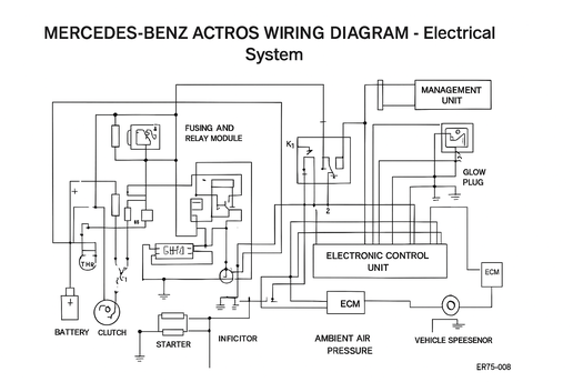
ACTROS Engine Control Unit PLD Pinout
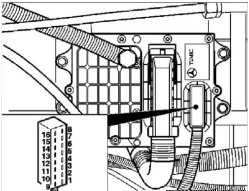
Mercedes-Benz Actros engine control unit (ECU) pinouts, located on the engine. The pinouts for the small and large connectors, wire colors, numbers, and the circuit connected to the wires are provided.
Control Unit Connector X1 (16-pin), from the vehicle side
| Pin | Description | Wire Color |
|---|---|---|
| 1 | CAN-LOW | Yellow |
| 2 | CAN-HIGH | Blue |
| 3 | CAN-GND (Ground) | Brown/Grey |
| 4 | CAN-GND (Ground) | Brown/Red |
| 5 | Terminal 30 | Red |
| 6 | Terminal 30 | — |
| 7 | Not used | — |
| 8 | Terminal 50 | Black |
| 9 | Terminal 31 | Brown |
| 10 | Not used | — |
| 11 | Terminal 31 | Brown |
| 12 | Terminal 50 from FMR | Black/Grey |
| 13 | Diagnostic connector (X13) | Purple/Yellow |
| 14 | Not used | — |
| 15 | Terminal 15 | Black/Blue or Purple |
| 16 | Not used | — |
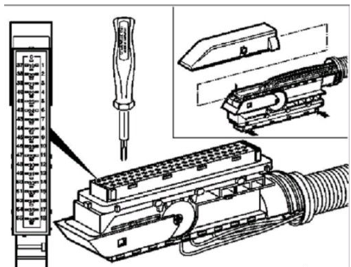
Connector N3 (55-pin)
| Pin | Description | Wire Color |
|---|---|---|
| 0 | Not used | — |
| 1 | TDC Sensor of Cylinder 1 (B16) | Black/White |
| 2 | Crankshaft Position Sensor (B15) | Black |
| 3 | Coolant Temperature Sensor (B65) | White/Yellow |
| 4 | Fuel Temperature Sensor (B10) | Brown/Green |
| 5 | AGND (Analog Ground) for Oil Pressure Sensor (B12) | Brown/Grey |
| 6 | Not used | — |
| 7 | Power Supply +5V for Boost Pressure Sensor (B13) | Green |
| 8 | Not used | — |
| 9 | Cylinder Bank 2 – Right Side (+) | Brown/Blue |
| 10 | Not used | — |
| 11 | Not used | — |
| 12 | Not used | — |
| 13 | Power Supply +5V for Vehicle Speed Sensor | Grey/White |
| 14 | Not used | — |
| 15 | Oil Level Sensor (B14) | Brown/White |
| 16 | Cylinder Bank 1 – Left Side (+) | — |
| Pin | Description | Wire Color |
|---|---|---|
| 17 | Not used | — |
| 18 | Terminal 50 to Starter (M1) | Black/Grey |
| 19 | Crankshaft Position Sensor (B15), (–) | Brown |
| 20 | TDC Sensor of Cylinder 1 (B16), (–) | Brown/Yellow |
| 21 | Charge Air Temperature Sensor (B9), (–) | Yellow |
| 22 | AGND (Analog Ground) for Test Bench Speed Sensor (optional) | Grey/Violet |
| 23 | AGND (Analog Ground) for Boost Pressure Sensor (B13) | Blue |
| 24 | Not used | — |
| 25 | Engine Start Button (S10), (+) | Red/Black |
| 26 | Oil Pressure Sensor (B12), (+) | White/Black |
| 27 | Not used | — |
| 28 | Test Bench Speed Sensor Signal (optional) | — |
| 29 | Boost Pressure Sensor (B13), Signal | Violet |
| 30 | Engine Start/Stop Button (–) | Blue/White |
| 31 | Not used | — |
| 32 | Not used | — |
| 33 | Oil Level Sensor (B14), (+) | White |
| 34 | Coolant Temperature Sensor (B65), (+) | Red/Yellow |
| 35 | Engine Stop Button (S11), (+) | Red/White |
| 36 | Fuel Temperature Sensor (B10), (+) | Brown/Blue |
| 37 | Not used | — |
| 38 | Unit Injector Cylinder 6 (Y11), (+) | White/Blue |
| 39 | Oil Level Sensor (B14), (+) | Grey/Brown |
| 40 | Not used | — |
| 41 | Not used | — |
| 42 | Not used | — |
| 43 | Not used | — |
| 44 | Unit Injector Cylinder 5 (Y10), (+) | Grey/Blue |
| 45 | Unit Injector Cylinder 4 (Y9), (+) | Grey/Yellow |
| 46 | Not used | — |
| 47 | Unit Injector Cylinder 3 (Y8), (+) | White/Red |
| 48 | Charge Air Temperature Sensor (B9), (+) | Brown/Black |
| 49 | AGND (Analog Ground) for Oil Level Sensor (B14) | Yellow |
| 50 | Proportional Valve 2 (+) | Green/White |
| 51 | Not used | — |
| 52 | Proportional Valve Feedback | Brown/Red |
| 53 | Unit Injector Cylinder 2 (Y7), (+) | Grey/White |
| 54 | Unit Injector Cylinder 1 (Y6), (+) | Grey/Red |
| 55 | — | — |
MERCEDES-BENZ / 1848 (Actros) / 09/1996 — 09/2003
OM 542.921 Engine
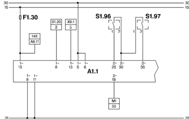
Electrical Wiring Diagram
S1.20 = Ignition and Starter Switch.
S1.96 = Engine Starter Switch.
A1.1 = Engine Control Module.
S1.97 = Engine Stop Switch.
F1.30 = Fuse 30
X9.1 = Diagnostic Connector.
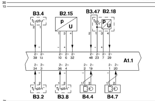
B3.47 = Charge Air Temperature Sensor.
B3.8 = Fuel Temperature Sensor.
A1.1 = Engine Control Module.
B4.4 = Crankshaft Position Sensor.
B2.15 = Engine Oil Pressure Sensor.
B4.7 = Camshaft Position Sensor
B2.18 = Boost Pressure Sensor.
B3.2 = Coolant Temperature Sensor.
B3.4 = Engine Oil Temperature Sensor.

Y26.2 = Unit Pump Cylinder 2.
Y26.3 = Unit Pump Cylinder 3.
A1.1 = Engine Control Module.
Y26.4 = Unit Pump Cylinder 4.
S3.5 = Oil Pressure Switch.
Y26.5 = Unit Pump Cylinder 5.
Y10.63 = Ventilation Solenoid Valve.
Y26.6 = Unit Pump Cylinder 6.
Y26.7 = Unit Pump Cylinder 7.
Y10.64 = Ventilation Solenoid Valve.
Y26.8 = Unit Pump Cylinder 8.
Y26.1 = Unit Pump Cylinder 1.
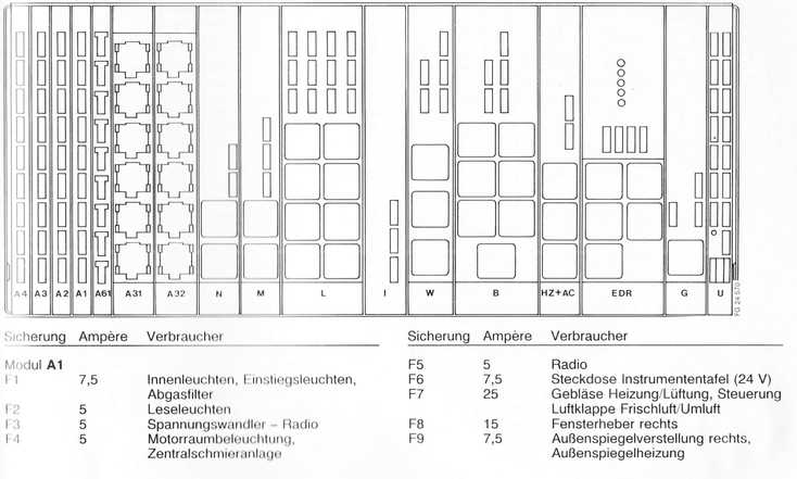
Location and designation of modules in the electrical compartment

System Monitoring / Instrument Illumination
| Code | Description |
|---|---|
| B1 | Starter push button on engine |
| B2 | Starter lock switch |
| B3 | Split group switch (gearbox without EPS) |
| B4 | Speed sensor – warning buzzer (engine 441/LA, 442/A/LA – gearbox without EPS) |
| F1–F3 | Fuses – Module M/1, M/5 |
| G1 | Alternator |
| G2 | Batteries |
| H1 | Charge control lamp |
| K1, K2 | Relays |
| M1 | Starter motor |
| N1 | Module – Engine control (M/1, M/5) |
| P1 | Tachometer |
| Q1 | Steering lock |
| Y1 | Magnetic valve – engine shutdown |
| Code | Description |
|---|---|
| B5 | Fluid level switch – windscreen washer / headlight cleaning system |
| B6 | Coolant level switch |
| B7 | Tipper control switch |
| B8 | Differential lock switch – 1st front axle |
| B9 | Differential lock switch – 2nd front axle |
| B10 | Differential lock switch – 1st rear axle |
| B11 | Differential lock switch – 2nd rear axle |
| B12 | Differential lock switch – front axle drive |
| B13 | Differential lock switch – transfer gearbox |
| B14 | Differential lock switch – rear axle drive |
| B15 | PTO control switch I |
| B16 | PTO control switch II |
| B17 | Split group switch (gearbox without EPS) |
| B18 | Parking brake control switch |
| B19 | Coolant temperature switch |
| B20 | Engine sensor – oil pressure indicator |
| B21 | Coolant sensor – temperature indicator |
| B22 | Fuel level sensor |
| B23 | Brake circuit 3 switch (engine brake) |
| F1–F3 | Fuses – Module I |
| G3 | Tachograph sensor |
| H2 | Warning buzzer |
| H3 | Indicator lamp – fluid level (windscreen washer / headlight cleaning system) |
| H4 | Indicator lamp – coolant level |
| H5 | Indicator lamp – tipper body |
| H6 | Indicator lamp – differential lock, 1st front axle |
| H7 | Indicator lamp – differential lock, 2nd front axle |
| H8 | Indicator lamp – differential lock, 1st rear axle |
| H9 | Indicator lamp – differential lock, 2nd rear axle |
| H10 | Indicator lamp – differential lock, front axle drive |
| H11 | Indicator lamp – differential lock, transfer gearbox |
| H12 | Indicator lamp – differential lock, rear axle drive |
| H13 | Indicator lamp – PTO I and II |
| H14 | Indicator lamp – gearbox range display (R, C, 1–4) |
| H15 | Indicator lamp – gearbox range display (5–8) |
| H16 | Indicator lamp – parking brake / release control |
| N2 | Module – instrument / operation monitoring (I) |
| P2 | Tachograph |
| R1 | Control switch – instrument illumination |
| S1 | Combination instrument |