
Fuse and relay diagrams and rating tables for the Mercedes-Benz Unimog (U423/U427/U430/U527/U530). This essential guide for quick troubleshooting includes a detailed fuse box diagram, a description of each electrical component, and the rated current (A) for each fuse.
Fuses
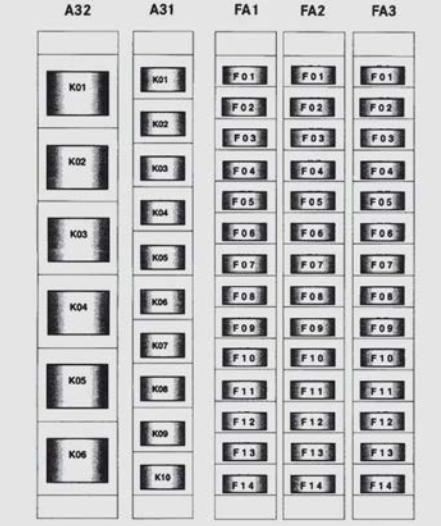
Fuse module FA1
| № | Consumers | A |
|---|---|---|
| F01 | Drive control system (OPC) / tachograph (DTCO) (terminal 30) | 20 |
| F02 | Drive control system (OPC) / programmable special module (PSM) / Unimog transmission control module (TCMU) (terminal 15) | 10 |
| F03 | Dual-mode steering / immobiliser (terminal 30) | 7.5 |
| F04 | 24 V power socket in centre console (terminal 15R) | 10 |
| F05 | 24 V power socket behind the driver’s seat (terminal 15R) | 25 |
| F06 | Radio terminal (TCC) 30 | 5 |
| F07 | Programmable special module (PSM) (terminal 30) | 15 |
| F08 | Diagnostics connection 16-pin (OBDII) terminal 30 | 10 |
| F09 | Engine management (MCM) / exhaust gas after-treatment (ACM) AdBlue® supply unit (terminal 15) | 10 |
| F10 | 15-pin trailer power socket / 7-pin trailer power socket, front (terminal 30) | 20 |
| F11 | 7-pin ABS trailer power socket (terminal 30) | 20 |
| F12 | 7-pin ABS trailer power socket (terminal 15) | 15 |
| F13 | 12-V power sockets; behind driver's seat / centre console / voltage transformer for headlamp range controller (voltage transformer input) terminal 30 | 15 |
| F14 | 12-V power sockets, behind driver's seat / centre console (voltage transformer output), 12-V terminal | 15 |
Fuse module FA2
| № | Consumers | A |
|---|---|---|
| F01 | Instrument cluster (ICUC) / tachograph (DTCO) / reservoir pressure sensor K1 & K2 / Camera Monitor System (KMS) (terminal 15) | 5 |
| F02 | Instrument cluster (ICUC) / central gateway (CGW) / modular switch field (MSF) (terminal 30) | 5 |
| F03 | Power windows control panel / central locking terminal 15R | 15 |
| F04 | Power windows control panel / radio / dual-mode steering starter inhibitor relay (WL) (terminal 15R) | 15 |
| F05 | Interior lighting (terminal 30) | 10 |
| F06 | ABS (terminal 30) | 20 |
| F07 | Auxiliary heating (terminal 30) | 20 |
| F08 | Heating (terminal 15R) | 20 |
| F09 | Windscreen heating (terminal 30) | 25 |
| F10 | Unimog transmission control module (TCMU) (terminal 30) | 20 |
| F11 | Unimog transmission control module (TCMU) (terminal 30) | 20 |
| F12 | Seat heating / mower seat (terminal 15) | 10 |
| F13 | Water separator / rotation chains basic wiring (terminal 15) | 15 |
| F14 | Windscreen washer system (terminal 15R) | 25 |
Fuse module FA3
| № | Consumers | A |
|---|---|---|
| F01 | Immobiliser (terminal 50) | 5 |
| F02 | Mower seat windscreen washer system (terminal 15) | 10 |
| F03 | Mowing door side window heating (terminal 30) | 15 |
| F04 | Special Truck Control Unit (STCU) (terminal 15) | 5 |
| F05 | Special Truck Control Unit (STCU) (terminal 30) | 5 |
| F06 | Voltage supply (CAN) valve block (terminal 30) | 20 |
| F07 | Hydrostatic transmission fan / torque converter clutch fan (terminal 30) | 25 |
| F08 | Power hydraulics fan (terminal 30) | 30 |
| F09 | Working hydraulics fan (terminal 30) | 15 |
| F10 | Rotating beacon (RKL) (terminal 30) | 10 |
| № | Consumers | A |
|---|---|---|
| F11 | 32-pin and 11-pin power socket for equipment (terminal 15) | 10 |
| F12 | Central locking terminal 30 | 15 |
| F13 | 24-V selectable power supply in roof, terminal 15 | 15 |
| F14 | Lifting cylinder / temperature control for torque converter clutch fan (terminal 15) | 5 |
Additional FleetBoard fuses
| № | Consumers | A |
|---|---|---|
| F01 | FleetBoard terminal 30 | 7.5 |
| F02 | FleetBoard terminal 15 | 5 |
Relay
Relay module A32
| № | Description |
|---|---|
| K01 | Power hydraulics fan |
| K02 | Hydrostatic transmission fan / torque converter clutch fan |
| K03 | Working hydraulics fan |
| K04 | Auxiliary heating |
| K05 | Windscreen heating, left |
| K06 | Windscreen heating, right |
Relay module A31
| № | Description |
|---|---|
| K01 | Dual-mode steering |
| K02 | Rotating beacon (RKL) |
| K03 | Immobiliser |
| K04 | Mowing door side window heating |
| K05 | Refrigerant compressor clutch |
| K06 | Heating recirculation pump |
| K07 | Auxiliary heating (overriding control blower) |
| K08 | Voltage supply (CAN) valve block |
| K09 | Auxiliary heating (engine preheating cut-off at D+) |
| K10 | Central locking |
Write a comment