
This detailed document provides the complete Fuse and Relay Diagram and layout information necessary for fast and accurate electrical troubleshooting. Given the complexity of heavy truck electrical systems, having a reliable map of the power distribution centers is the first and most critical step in diagnosing faults, shorts, and system failures.
What the GIGA Fuse and Relay Manual Covers:
This guide provides clear, visual documentation for all power distribution points on your GIGA truck:
-
Fuse Box Locations: Clear identification of all fuse and relay panels, including those in the cab interior, the engine bay (main power), and chassis-mounted boxes.
-
Circuit Identification: Detailed diagrams showing the number, amperage, and primary function (e.g., "Tail Lamp," "ECU Power," "ABS Solenoid") of every single fuse.
-
Relay Functions and Pinouts: Clear labeling and diagrams identifying the function of all major and minor relays (e.g., Starter Relay, Headlamp Relay, ECM Power Relay) and their respective control circuits.
-
High-Current Breakers: Information regarding the location and rating of main circuit breakers that protect high-draw components like the glow plugs or hydraulic pump.
-
Model Specificity: Documentation tailored to the 2003–2015 model years, covering common engine configurations during this period (e.g., 6WG1, 6UZ1).
Power Distribution
Fuse, Fusible Link and Slow-Blow Fuse Location
NOTICE: USE SPECIFIED FUSE ONLY, UNSPECIFIED FUSES CAN CAUSE FIRE AND MALFUNCTION OF EQUIPMENTS.
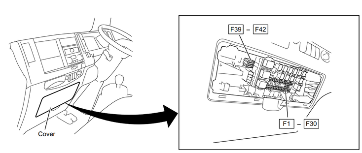
Fuse Box 1:
| Position | Amperage | Function |
|---|---|---|
| F39 | 15A | CONDENSER FAN (AIR CON) |
| F40 | - | - |
| F41 | 20A | POWER WINDOW (REAR) |
| F42 | 25A | ABS |
Main Fuse Panel:
| Pos. | Function | Amperage |
|---|---|---|
| 1 | HI/LIGHT CLEANER | 20A |
| 2 | AIR SUSPENSION | 15A |
| 3 | DOME LIGHT | 15A |
| 4 | DOOR LOCK | 15A |
| 5 | FRT FOG LIGHT | 10A |
| 6 | POWER WINDOW | 20A |
| 7 | ABS | 10A |
| 8 | FRONT WIPER/WASHER | 20A |
| 9 | HI/LIGHT LH | 10A |
| 10 | IMMOBILIZER | 10A |
| 11 | HI/LIGHT RH | 10A |
| 12 | STOP LIGHT | 10A |
| 13 | STARTER | 10A |
| 14 | HI/LIGHT LH | 10A |
| 15 | HI/LIGHT RH | 10A |
| - | SPARE | - |
| - | SPARE | - |
| - | SPARE | - |
Additional Fuse Panel:
| Pos. | Function | Amperage |
|---|---|---|
| 16 | MIRROR HEATER | 15A |
| 17 | AIR DRYER | 15A |
| 18 | PTO, BACK LIGHT | 15A |
| 19 | SRS | 10A |
| 20 | ENGINE CONTROLLER | 10A |
| 21 | METER | 10A |
| 22 | RR FOG LIGHT | 10A |
| 23 | REMOTE CONTROL MIRROR | 15A |
| 24 | CIGAR LIGHTER | 15A |
| 25 | HORN | 15A |
| 26 | TURN LIGHT, HAZARD | 15A |
| 27 | TAIL LIGHT | 10A |
| 28 | ILLUMI | 10A |
| 29 | CORNERING LIGHT/RR FOG LIGHT | 10A |
| 30 | BLOWER MOTOR | 20A |
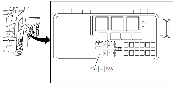
Fuse Panel:
| Position | Fuse | Amperage | Function |
|---|---|---|---|
| 1 | F31 | 15A | Power source |
| 2 | F32 | 15A | TCM |
| 3 | F33 | 15A | ECM main |
| 4 | F34 | - | - |
| 5 | F35 | - | - |
| 6 | F36 | - | - |
| 7 | F37 | 10A | Air conditioner |
| 8 | F38 | - | - |
Write a comment