
This guide provides clear, visual, and systematic documentation of all power distribution centers:
-
Fuse Box Locations: Clear identification of all fuse and relay panels, including the primary box in the cab interior (behind the dash panel) and the engine bay main power center.
-
Circuit Identification: Detailed diagrams showing the number, amperage (rating), and primary function (e.g., "ECM," "Glow Plug," "ABS," "DPF") of every fuse.
-
Relay Functions and Locations: Clear labeling and diagrams identifying the function, control circuit, and location for all major relays (e.g., Main Power, Starter, Heater Blower, and A/C relays).
-
High-Current Protection: Information regarding the location and rating of main fusible links or high-current circuit breakers protecting the main power feed.
-
Model Specificity: Documentation is tailored specifically to the electrical architecture of the 2007–2018 model years, covering common models like the NPR, NQR, and NRR.
Ensure fast, accurate electrical system repair and minimize costly downtime for your N-Series / ELF fleet by utilizing this official Fuse and Relay Diagram Manual.
Fuse Location (interior)
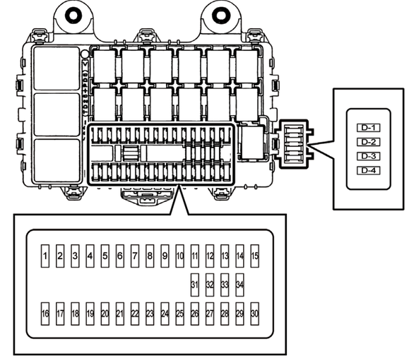
| No. | Description (English) | Description (French) | Rating |
| 1 | RR P/WINDOW | GLACE ÉLECT. AR. | 25A |
| 2 | — | — | — |
| 3 | ROOM LAMP, AUDIO | PLAFONNIER, AUDIO | 10A |
| 4 | DOOR LOCK | SERRURE DE PORTE | 15A |
| 5 | TRAILER BRAKE | FREIN DE REMORQUE | 15A |
| 6 | P/WINDOW | GLACE ÉLECTRIQUE | 25A |
| 7 | ABS | ABS | 10A |
| 8 | WIPER | ESSUIE-GLACE | 25A |
| 9 | H/LAMP LO (LH) | PHARE BAS (GAUCHE) | 10A |
| 10 | LAMPS (BATT) | LAMPES (BATT) | 10A |
| 11 | H/LAMP LO (RH) | PHARE BAS (DROIT) | 10A |
| 12 | BRAKE LAMPS | LAMPES DE FREIN | 10A |
| 13 | STARTER | DÉMARREUR | 10A |
| 14 | H/LAMP HI (LH) | PHARE HAUT (GAUCHE) | 10A |
| 15 | H/LAMP HI (RH) | PHARE HAUT (DROIT) | 10A |
| 16 | MIRROR HEATER | CHAUFFAGE MIROIR | 15A |
| 17 | IGNITION2 | ALLUMAGE 2 | 10A |
| 18 | IGNITION1 | ALLUMAGE 1 | 10A |
| 19 | — | — | — |
| 20 | ECM | MOD. COMM. ÉLECTRIQUE | 10A |
| 21 | METER | MÈTRE | 10A |
| 22 | ECU (BATT) | MOD. COMM. ÉLECTRONIQUE | 10A |
| 23 | MIRROR | MIROIR | 10A |
| 24 | AUDIO, ACC | AUDIO, ACC | 15A |
| 25 | HORN | KLAXON | 15A |
| 26 | TURN, HAZARD | CLIGNOTANTS, DÉTRESSE | 15A |
| 27 | TAIL LAMPS | FEUX ARRIÈRE | 10A |
| 28 | ILLUMINATIONS | ÉCLAIRAGE | 10A |
| 29 | CORNERING LAMPS | LAMPES DE VIRAGE | 10A |
| 30 | AIR CONDITIONER | CLIMATISEUR | 10A |
| 31 | SPARE | PIÈCES DE RECHANGE | 10A |
| 32 | SPARE | PIÈCES DE RECHANGE | 15A |
| 33 | SPARE | PIÈCES DE RECHANGE | 25A |
| 34 | SPARE | PIÈCES DE RECHANGE | 20A |
| D-1 | CIGAR | ALLUME-CIGARE | 20A |
| D-2 | ACCESSORIES SOCKET | PRISE POUE ACCESSOIRES | 15A |
| D-3 | POWER SOURCE | ALIMENTATION ÉLECTRIQUE | 20A |
| D-4 | — | — | — |
Relay Location (interior)

| No. | Description |
| 1 | STOP LAMP |
| 2 | DAY TIME RUNNING LAMP |
| 3 | KEY ON |
| 4 | TCM (A/T models) |
| 5 | PARKING/NEUTRAL |
| 6 | WIPER MAIN |
| 7 | HORN |
| 8 | WIPER HI LO |
| 9 | TRAILER BRAKE |
| 10 | POWER WINDOW |
| 11 | CHARGE (ENG RUN) |
| 12 | POWER WINDOW |
| 13 | HEAD LAMP LO |
| 14 | VACUUM PUMP |
| 15 | HEAD LAMP HI |
| 16 | TAIL LAMP |
| 17 | CORNERING LAMP |
| 18 | CIGAR LIGHTER |
| 19 | POWER ACC |
| 20 | BLOWER MOTOR |
Relay and Fuse Locations (exterior)

| No. | Relay name | No. | Fuse name | Rating |
| 1 | STARTER | 1 | MARKER LAMP | 20A |
| 2 | A/C COMPRESSOR | 2 | TAIL MAIN | 20A |
| 3 | CONDENSER FAN | 3 | ECM MAIN (4HK1) | 10A |
| 4 | RR DOME LAMP | 3 | FUEL HEATER (4JJ1) | 15A |
| 5 | SCR WATER VALVE | 4 | SCR | 20A |
| 6 | MARKER LAMP | 5 | RR DOME LAMP | 15A |
| 7 | EXHAUST BRAKE CUT | 6 | CONDENSER FAN | 20A |
| 8 | — | 7 | A/C | 10A |
| 9 | ECM (4HK1) | |||
| 9 | FUEL HEATER (4JJ1) |
Write a comment